Caminax® –
Data Sheet
Currently we offer four different versions of our Caminax®. The differences concern mainly the resolution and computing power. One camera is capable of recognizing colors.
1. Technichal Data, Modules and Functionality
Version |
612 S |
812 C |
632 |
1032 |
CCD-Chip |
1/3"-Chip grayscale |
½"-Chip 782 x 582 color |
1/3"-Chip grayscale |
1/3"-Chip grayscale |
Resolution |
640 x 480 Pixel |
640 x 480 Pixel |
640 x 480 Pixel |
1024 x 768 Pixel |
Processor |
1200 MIPS |
1200 MIPS |
3200 MIPS |
3200 MIPS |
Image acquisition (Hz) |
25 Hz |
45 Hz |
63 Hz |
30 Hz |
Digital I/O’s |
4 IN / 4 OUT |
4 IN / 4 OUT |
4 IN / 4 OUT |
4 IN / 4 OUT |
Interface |
Keypad + RS232 |
Keypad + 100 Mbit Ethernet |
Keypad + 100 Mbit Ethernet |
Keypad + 100 Mbit Ethernet |
Video Output |
SVGA 800/600 |
SVGA 800/600 |
SVGA 800/600 |
SXGA 1280/1024 |
Power supply |
24 V DC |
24 V DC |
24 V DC |
24 V DC |
|
|
|
|
|
Extra functionality |
Programm execution via RS232 |
Programm execution via Ethernet
Extramodul „Color“ |
Programm execution via Ethernet |
Programm execution via Ethernet |
Modules |
Image
Brightness
Area
Point
Distance
Angle*
Circle-Edge
Straight line*
Tracking
Wait*
Result |
Functionality |
Multi-Window Manager
Transfer (Image*, Configuration)
Calibration*
Statistics (for each Programm)
Brightness Tracking
Tracking in x,y
Digitale Programm execution (max. 14 Programms)
Up to 100 prgramms storable, depending on their size
Counting edges
Counting edges on circle
|
* The functions marked with a star * are currently implemented. We will soon provide you with a software update via our website.
2. Camera Plug Assignment
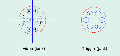
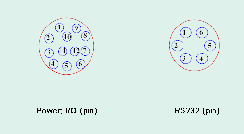
The cameras have four connectors on the rear side:
| V24(RS232) |
HR10A-7R-6PB |
6-pin Hirose plug pin contact |
| Keypad (Trig.) |
HR10A-7R-6SB |
6-pin Hirose plug pin contact |
| SVGA (Video) |
HR10A-10R-10SB |
10-pin Hirose plug pin contact |
| Power/SPS (I/O) |
HR10A-10R-12SPB |
12-pin Hirose plug pin contact |
Pin Assignment Trigger/Keypad Plug Signal |
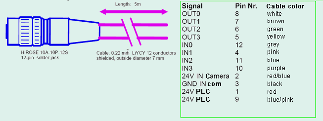
Pin Assignment for the I/O Plug /SPS |
Signal |
Pin |
Signal |
Pin |
GND |
3 |
OUT0 |
8 |
5V OUT |
2 |
OUT1 |
7 |
(Trigger IN –) |
1 |
OUT2 |
6 |
(Trigger IN +) |
6 |
OUT3 |
5 |
(Trigger OUT) |
5 |
IN0 |
12 |
Keypad IN |
4 |
IN1 |
4 |
|
|
IN2 |
11 |
|
|
IN3 |
10 |
|
|
24V IN/Cam |
2 |
|
|
GND IN (common) |
3 |
|
|
24V IN/PLC |
1 |
|
|
24V IN/PLC |
9 |
Pin Assignment for LAN/Ethernet |
Pin Assignment for XGA/SVGA Video Output |
Signal |
Pin |
Signal |
Pin |
R+ |
6 |
R Out |
4 |
T+ |
2 |
R GND |
3 |
R- |
5 |
G Out |
2 |
T– |
1 |
G GND |
1 |
NC |
3 |
B Out |
9 |
NC |
4 |
B GND |
8 |
|
|
HS Out |
10 |
|
|
HS GND |
7 |
|
|
VS Out |
6 |
|
|
VS GND |
5 |
Pin Assignment for the camera connectors (rear view)


3. Cable Assignment
3.1 Trigger/Keypad Cable
Attention! The pin assignments for the x12 und die x32 series are different for the trigger/keypad:
For the models 612 and 812

One end equipped with Hirose plug, the other with DB9; length 5 m
For the models 632 and 1032

One end equipped with Hirose plug, the other with DB9; length 5 m
3.2 Power/PLC-Cable

One end equipped with Hirose plug, length 5 m
3.3 V24 (RS232) Cable (only for model 612 S)

One end equipped with Hirose plug, length 5 m
3.4 SVGA Monitor Cable

One end equipped with Hirose plug, the other with DB15 plug jack; lenth 5 m
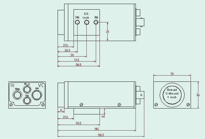
4. Housing Dimensions

|
